Arduino Controlled Servo
By term Servo we usually refer to DC motor with additional electronics that is used to control DC motor in such way that user is able to say what is requested position of motor shaft. You can buy pre built servos but these servos usually are targeted for particular use i.e. avionics etc. Goal of robotic arm is to be universal. Servo settings will eventually vary depending on what job arm is actually doing. Here you will learn about Encoder, H-Bridge and PID controller.
Circuit
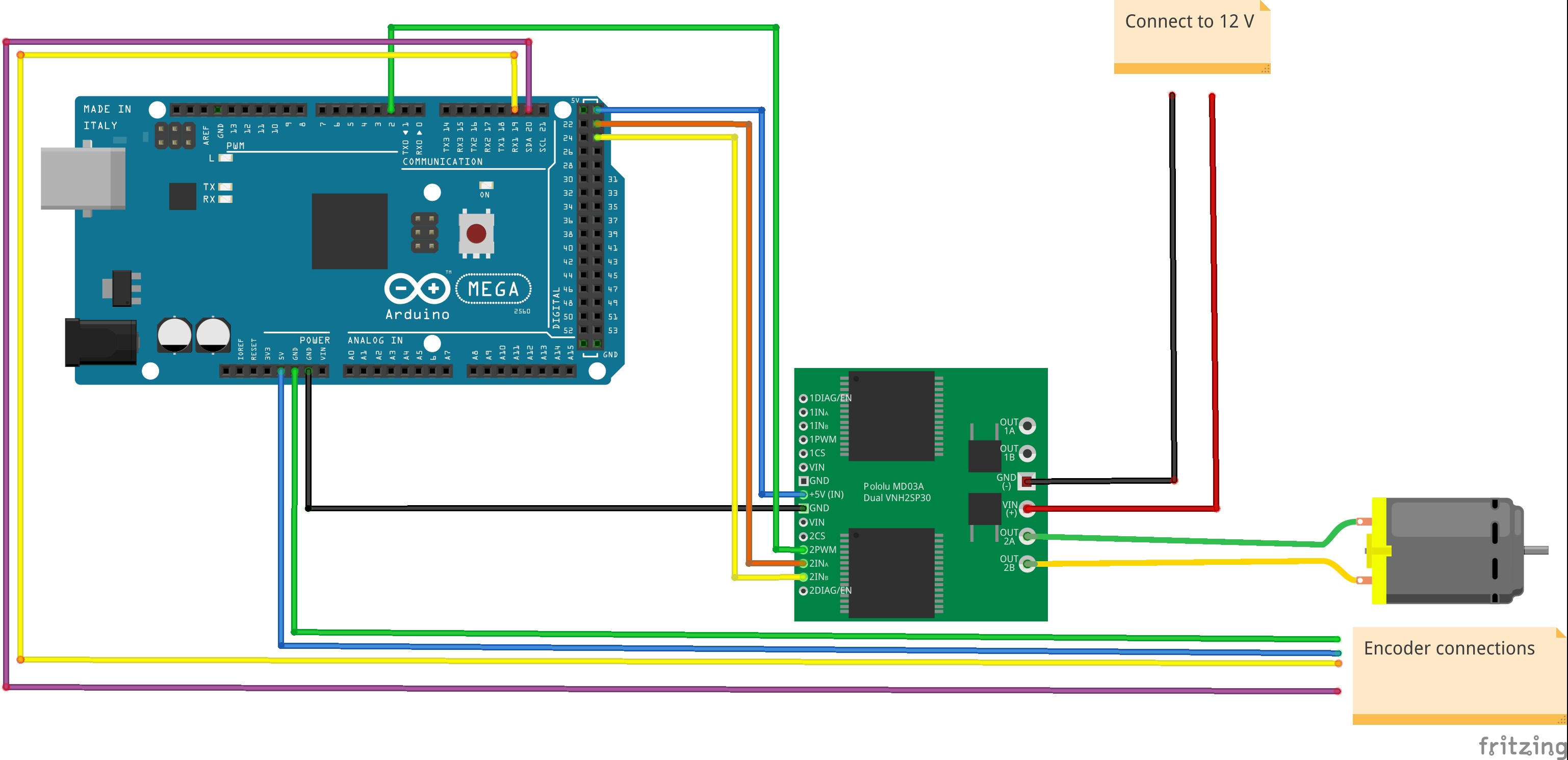
Below you can see diagram that I used for building servo. Parts I’ve chosen for my project are:
- Pololu 131:1 Metal Gearmotor 37Dx73L mm with 64 CPR Encoder
- Dual VNH3SP30 Motor Driver Carrier MD03A
- Arduino Mega 2560
Basic control of DC motor is simple. Basically if you add the voltage to the motor terminals you will get your motor running. Depending on voltage motor will spin faster or slower and direction of motor shaft movement depends on voltage sign. Please take a note that this is far off what servo is. Direct control over motor where only voltage is used to enable movement does not provide any confidence on shaft position or even rotation speed. Ideally motor speed is proportional to voltage provided but we cannot guarantee this proportion to be fixed over time. Usually we add variable load to motor. Consider robotic arm which is used to carry chess pieces. When arm carries king or queen load is different when arm carries pioneer. If our control would relay only on voltage value applied to motor then in these cases it would lead to different movements for queen, king or pioneer.
That is a reason why we need a feedback based control. Basically controller needs to look up for current shaft position and adjust voltage accordingly.
How Arduino controller knows what is position of motor shaft ?
This is the moment where I need to describe Encoder. Encoder is an eye of controller constantly looking over motor shaft position. On diagram you can see purple and yellow wires coming out form encoder and hooked up to Arduino board. Arduino can learn what is shaft position by looking on signals states on these wires. Additionally encoder is connected to GND and +5V with green and blue wire for power supply. I will cover encoder details in dedicated post.
How Arduino controls motor ?
Assuming Arduino is able to precisely tell what is shaft position it also needs to provide voltage and current that is able to move Motor shaft. Motors like Pololu one can consume lot of power. Lets say: motors like that consumes more power than Adruino board itself. To be precise: According to Pololu this particular motor consumes 300 mA in free run and up to 5A in peaks. That is a lot. This is direct reason we cannot hook up Adruino directly to motor. We need to have additional power amplifier. Once again we use Pololu part - Motor Driver. Motor Driver provides isolation of control signals from motor to protect Arduino.
Consider this. There are multiple scenarios were you would like to keep Arduino isolated from motor. In cases where heavy load is attached to motor shaft and motor shaft spins with maximum speed. Then you stop providing voltage to motor. Obviously motor will keep rotating due to inertia. In this case motor will behave like generator and will provide a voltage on its terminals. Such voltage could harm your Arduino.
In order to avoid negative impact of such scenarios Motor Drivers usually integrates dedicated circuits to minimize side effects of such scenarios. Most common circuit used for that purpose is H Bridge.
H Bridge control direction of motor movement. Two wires: yellow and orange - are used to control movement direction. Additional green wire is for motor voltage control. Pololu circuit is also connected to GND by black wire and to +5V by blue wire.
Control algorithm
At the moment this is just a teaser. There are multiplies strategies how to set
voltage control on motor terminals in order to get requested shaft position. If my
requested position is, lets say 44, and current position is 11 I should apply
some voltage to motor in order to get shaft position changed to 44. But what
voltage should it be? Should it be max?
In servos we often use PID algorithm as it brings good quality control. I will describe control strategies in separate articles.
Summary
I briefly described what servo is and problems we need to solve in order to create it. I hope you are ready to go for further reading and finally lets do some implementation.