Connecting Motor Encoder to Arduino
As I mentioned in one of my last post Encoder is Arduino Controller eye on motor shaft. This article will describe how to integrate typical encoder with Arduino.
Encoder interface
Refer to following diagram diagram:
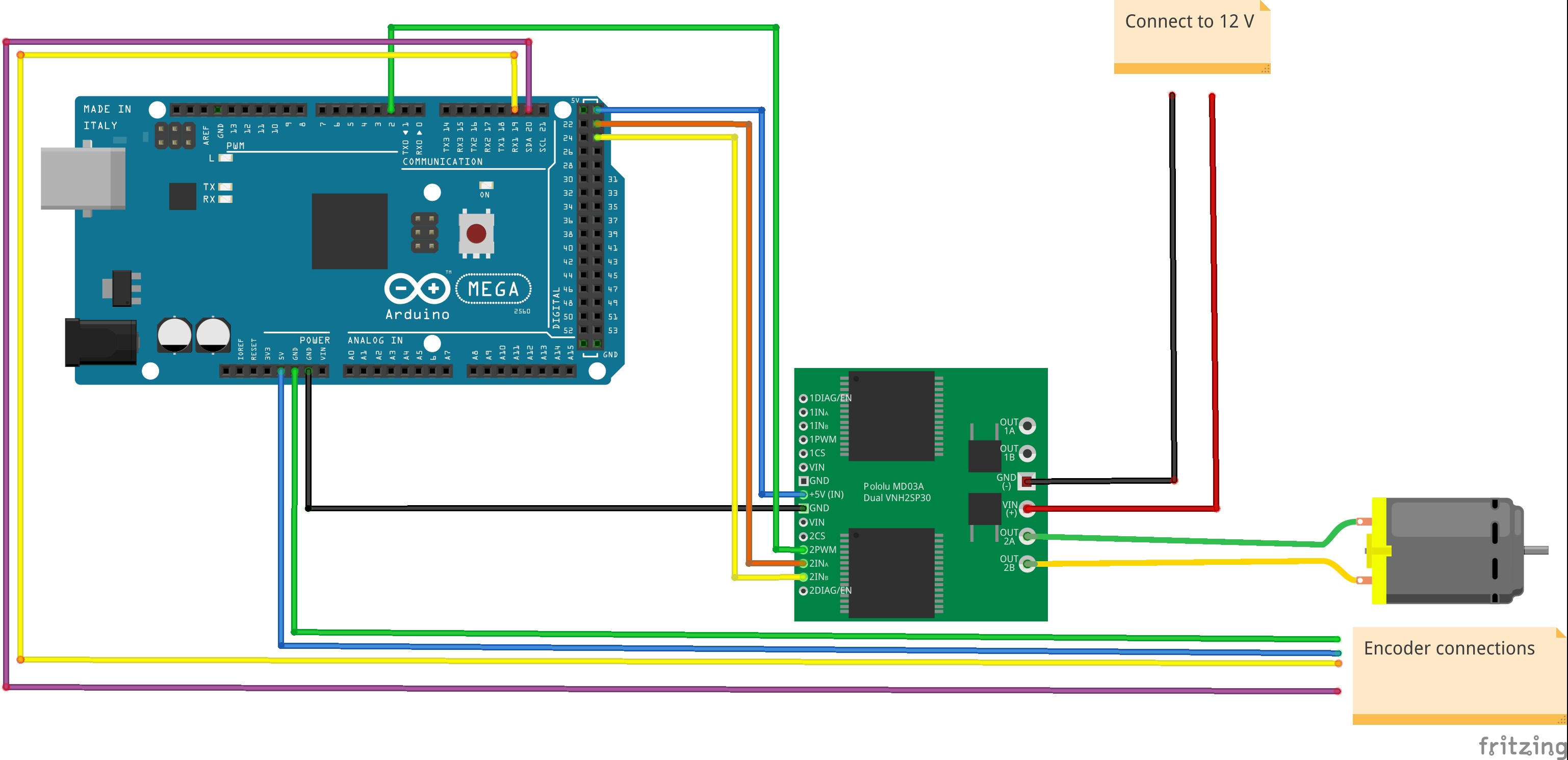
On diagram you can see purple and yellow wires coming out form encoder and hooked up to Arduino board. These wires are attached to 19 and 20 pins. Arduino controller needs to constantly monitor states of these pins. In Arduino Mega these pins are special because they are interrupt enabled. We need to attach them to interrupt service routine. This routine is special function which does not return anything but its called every time interrupt is raised. We need to attach to both pins interrupts.
attachInterrupt(digitalPinToInterrupt(glob->dc1.encoderAPin),encoder1_ISR, CHANGE);
attachInterrupt(digitalPinToInterrupt(glob->dc1.encoderBPin),encoder1_ISR, CHANGE);
Rationale behind all that buzz is quite simple. Encoder interface provided by Pololu is simplistic and doesn’t contain any logic on encoder side. That would be fantastic if you could just read absolute shaft position but unfortunetly you need to do a little more. Reason is Encoder simplicity. Encoder is just magnet well connected to motor shaft. When shaft moves it moves along with magnet wheel and special magnet detectors generates logical states (0 or 1) depending on magnet well position. On top of that magnet well is magnetized in with special sequence that we call Gray code.
There are limitations:
- Firstly, for this particular encoder, you got only 2 bits that represent position of shaft. That makes only 4 logical states that represent position. We deal with 64 CPR (counts per revolution) which mean that encoder magnet well duplicates 4 logical states 16 times for full shaft spin.
- Encoder doesn’t have any state that represent reference position which we might call 0-position. Basically motor shaft is able to rotate hundreds times but reading encoder states will be same as in first spin.
Above limitations has to be addressed by Arduino controller when building servo.
Gray code
Lets take a look into 4 logical states that can be read by Arduino on pins 19 and 20. Some time ago gentlemen Frank Gray created something that we call Gray Code. Here is a table that represent comparison between binary and gray code.
| Representation Value | Binary code | Gray Code |
|---|---|---|
| 0 | 00 | 00 |
| 1 | 01 | 01 |
| 2 | 10 | 11 |
| 3 | 11 | 10 |
Please take a look into value 1 and 2 representation in binary code.
In binary code we changed two binary digits in order to progress 1
in representation value (01 are altered to 10). In gray code we never see
progress 1 that changes two digits in code itself. This is important since in
practice its often when wee have measurements errors. Single digit(bit) read
can differ from actual state. In binary code a measurement error on single bit
could differ output by two in representation value.
Please refer to Pololu documentation on motor. Following diagram represents logical states upon shaft movement:
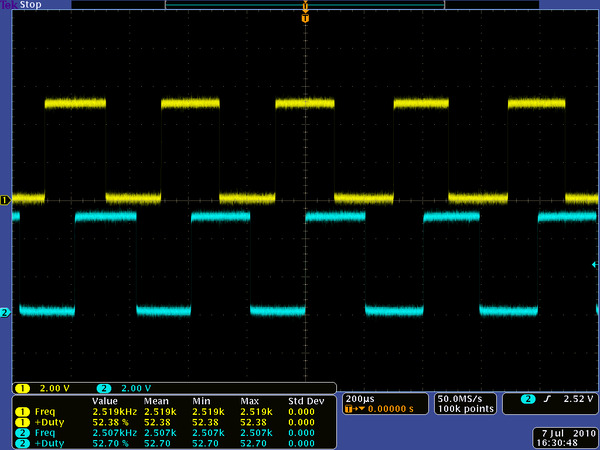
But going back to our Arduino case… Reads performed on yellow and purple (Encoder A and Encoder B) results in Gray code that matches representation value.
Get Things Moving
For this particular use case it is easy to represent value of gray code as lookup
table. Whenever we would like to know representation value of yellow and purple
readings we could simply call grayValue(...) function:
uint8_t greyValue(uint8_t a, uint8_t b)
{
    return greyLookup[a][b];
}
Interrupts
An interrupt is a signal to the processor emitted by hardware indicating an
event that needs attention. When interrupt condidtions happen then CPU
postpones current job and imidietly goes into interrupt service routine. In our
case encoder1_ISR function .
It might not be obvious to use interrupts for encoder interoperability. I will
try to describe it one more time after getting some insists on encoder itself.
Please take a look into attachInterrupt function. All it does it assigns
function encoder1_ISR to encoderAPin and encoderBPin. For our case these
are 19 and 20 pins of our Arduino Mega. Interrupt function encoder1_ISR will
be called upon every CHANGE of state on pins 19 and 20. I think you might ask
why don’t simply run digitalRead function to get state of pins. Answer is our
encoder weaknesses, described above. We got only two bit representation of
shaft position.
Lets just think about problems that could arise when we use timer triggered
digitalRead instead of interrupts. Lets assume we set a timer of 50 ms and we
are getting state of encoder lines. Suppose scenario is as follow: On three
reads in row we got 3. Would that mean that motor is not running at all or we are lucky
that three reads given us same value ? I hope you understand issues that could
arise. Obviously we can move Robobo design toward time based pulling mode
direction but we would need to minimize a time period that we use between reads.
Not going into details but eventually it would end up with unnecessary overload
of CPU.
Closing remarks
In today article I described Encoder, Gray code and provided some justification why interrupts were selected on Robobo design. Above code sections are taken directly from Robobo so in case of any doubts please refer to project.