Arduino Controlled Servo - PID
Responsibility of Arduino servo controller is to calculate voltage value and duration it is applied to motor terminals. Goal of controller is to get motor shaft position aligned to the requested. In this material I will describe PID controller - one of most common control algorithm in industry. PID description presented here was created with assumption control theory background is not required from reader.
PID - introduction
Lets try to sum up what control algorithm is for our case.
- Algorithm takes requested position as input
- Algorithm takes current shaft position as input
- Algorithm produces voltage value as output
On top of that we need to be aware that we are controlling dynamic object (DC motor) so we should also expect that our algorithm itself should be dynamic as well. Dynamic means that depending on time factor algorithm might produce different output for same inputs. As this could be confusing. For a moment please ignore this as I will describe it in more details later on. To keep order I will add note to the ones above:
- For same inputs algorithm output might wary depending on its internal state
PID - Proportional
The letter P in PID stands for “proportional”. In here I would like you to imagine a spring as you know. Spring have a property that makes it interesting from control perspective. If you try to squeeze a spring it will return to its original shape. Same goes for stretching. You might keep your spring stretched for a moment and you will notice that you need to apply force to keep it streched. The spring is giving you same amount of force in opposite direction because it want to go back to its original shape. If you already had a physic class you might already know that force that spring is giving back is proportional to length that spring is out of its rest position.
Following figure represents spring attached to robotic arm.
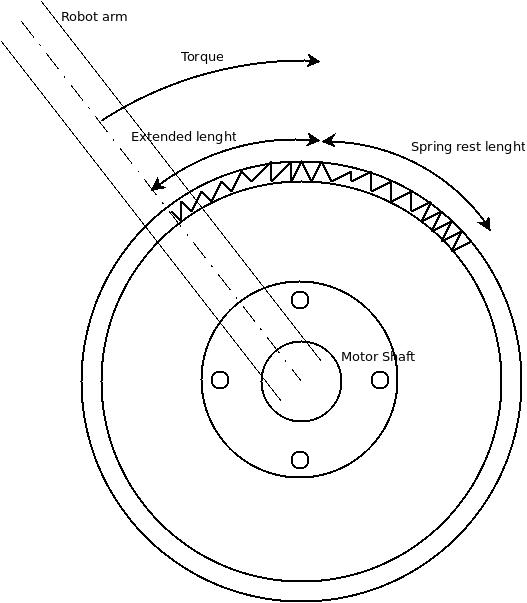
At this moment lets think how spring could act as our control algorithm. If we could attach a spring to our motor shaft in such a way that its rest position is exactly aligned with requested position then then our spring would apply a force to move our shaft to requested position. Obviously spring would have to be strong enough to do so.
OK. But does it have anything to do with out control algorithm?
Yes - because at this point we will be implementing algorithm that will behave exactly the same as our imaginary spring. Firstly we calculate how far our imaginary spring is from its original length (rest position).
diff = motor->getRequestedPosition() - motor->getCurrentPosition();
dcOutput = calculateControl(diff);
diff is an imaginary offset from original length. We take it and then
calculating control which suppose to be our voltage
int32_t calculateControl(int32_t diff)
{
    return diff *kP;
}
kP is our spring property.
And finally we need to apply our control to dc motor:
if (dcOutput < 0 )
{
    motor->setDirectionLeft();
}
else
{
    motor->setDirectionRight();
}

dcOutput = abs(dcOutput);

//need to scale target value to range 0-255 PWM
if (dcOutput >255)
    dcOutput = 255;

if (!motor->isStopped())
    motor->setVoltage(dcOutput);
setDirectionRight and setDirectionLeft are controlling
H-bridge pins. One
more thing that might require to comment is scaling dcOutput to 255.
Rationale behind that is quite simple. setVoltage method directly maps to
Arduino analogWrite function that expect uint8_t as input so line here is
to perform scaling functionality visible for anyone. Moreover in future we
might even want to limit voltage that we apply to DC motor with for instance
100 then we will just substitute this number.
PID - Integral
Letter I in PID stands for Integral. The word integral might sound scary but please continue reading as I intent to describe it in such a way that no advanced math is required.
Our spring controller described in previous chapter have one fundamental flaw that makes it useless for Robobo robotic arm. Please analyze following diagram.
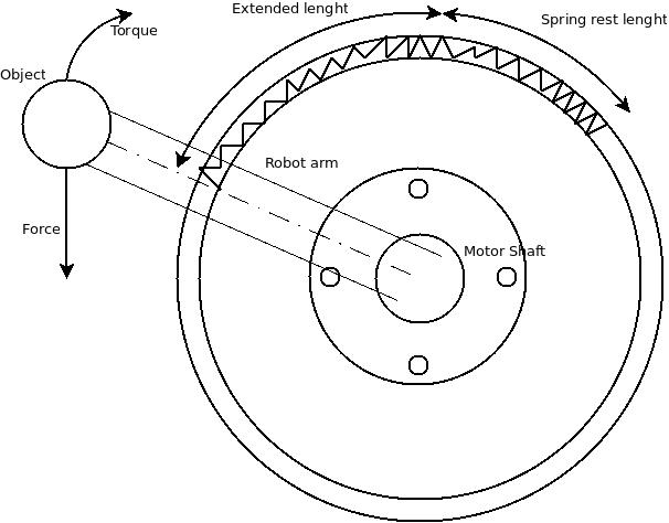
In our previous case we did not attached any mass to robotic arm. In reality motor shaft always carries some additional objects. This additional mass is impacting a system balance. If mass is applied to robot arm then motor shaft is subject of two forces. One force will try to bring motor shaft down while second force generated by P-controller “spring” will try to to achieve a rest position. These two will remove themself and robot will not achieve desired position.
Moreover having a stronger “spring” (kP) is not an answer for this
problem.
If spring will have higher kP parameter you will spot other problem.
While it might seems that stronger P-Controller will solve everything in reality
results might become even worst than original situation. Problem you will
encounter when increasing kP is oscillation caused by full power
outputs.
Dealing with dynamic objects like DC motor is always associated with phenomenon of inertia. Inertia makes easy to put motor in oscillations especially when dealing with frequent control changes and full power outputs. If you take a look into physics of DC motor movements you need will notice that there are complex energy changes happening upon control. We have electrical energy that is exchanged into kinetic movement. Also we got a mass of motor shaft which also accumulates energy. This types of energy flows are not instant and it takes time to exchange one energy onto to another. When you apply full power to motor terminals it will last some time until motor will rotate with full speed.
Lets take a closer look at particular example. Lets say motor shaft is at
distance 10 out of requested position. We have kP of 25. Our diff * kP
control is almost full power and its equal to 250. Our time interval in which
we are producing output is 1 millisecond. So for first millisecond we keep 250
control to motor. In next millisecond we found out that motor shaft is indeed
closer to requested and its off by 1 from requested position. Our control is 25
for next millisecond. At this point seems everything is OK but in next reading
we have -25 off from requested position. Why is that? What did happen?
Apparently first millisecond is key here. We had a full output for 1
millisecond and energy did not managed to convert into movement till next
period. Even when we drastically minimized control energy was already provided
to motor and was waiting to be converted. That is inertia.
How to solve the problem of being unable to achieve requested position then?
Approach is simple and really straight forward: Longer motor shaft is out of requested position we apply bigger control. Strategy looks like this:
- Using P-controller we get into balance state which is out of requested position as described above
- Now we wait and we see motor shaft still does not get closer to requested position
- We wait for millisecond and then increase our control a bit
- In next millisecond if shaft isn’t still closer we increase our control even more
int32_t calculateControl(int32_t diff)
{
    uint32_t now = micros();
    uint32_t timeDelta = now - prevMicros;

    prevMicros = now;
    integral = integral + diff * timeDelta;
    return diff *kP + integral * kI;
}
prevMicros and integral are PID object members and stays same between
calculateControl method calls.
Algorithm above fulfil our concept. Longer motor shaft stays out of requested
position higher control value is. Please note that integral will fully
eliminate itself when motor shaft will actually overtake our requested
position. kI is fine tuning parameter that we can adjust depending on needs.
PID - Summary
At this point essence of PID algorithm mechanics is explained. This chapter
doesn’t cover final implementation that can be found in Robobo. What you need
to know is a fact about existence of canonical PID algorithm. Canonical PID
gives you ability to perform fine tuning of algorithm. There are recipes
created using mathematical models that allows to find optimal kP, ‘kI` and
‘kD’ settings for canonical controller. That is very usfull as finding a right
parameters is not easy. Canonical form is bit more complex to explain so I
decided to create seperate post for it.
I hope this introduction to PID controller was useful and you managed to understand a concept which is not that hard to understand if you strip it from mathematical model.