Limit Switch
Servos are used to run Robobo platform axis. Servo mechanism described here lacks one fundamental concept that would make it complete. That is absolute positioning. As mentioned simple encoder is able to find relative movement only. This article describes limit switch hardware component and Robobo software design for it.
Limit Switch Hardware
Typical limit switch logic is presented on diagram:
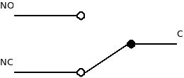
Where (I suppose) NC stands for Normally Closed and NO as Normally Opened. These mean when no force applied on switch then NC is connected to C.
We usually think about limit switch as protection mechanism for scenario where we don’t want to make servo go out of certain limit. This concept might be realized in two forms:
- Hardware
- Software
In hardware option we connect limit switch to our DC Motor power line using C and NC. By this DC Motor can be powered as long as there is no contact of Limit Switch. This design is well suited for power robots where risk of robot’s surroundings or robot itself damage exists. In this case Limit switch can be safeguard for multiple failure scenarios such as: Control board failure, program error or user mistake.
In software option we connect limit switch to our main controller. Switch C
terminal serves as output and NC and NO are connected to ground and 5V (3.3V
for Due). Switch C output in this case is logical 1 or logical 0. In this
option it is up to controller to stop a shaft to prevent any damage. In this
option limit switch acts like normal button.
Robobo consideration
For Robobo case software approach seems suitable. This concept in fact is to address two problems. First problem is that we don’t want our shaft to cross boundary and second problem of finding absolute position of shaft.
Moreover we are dealing with low power parts such as low current DC Motor so possible risk of damage is low. That is reason we focus on software limit switch implementation only.
Robobo software design consideration
Before spending time on software implementation lets bring up software design assumptions taken already and lets recap recap design in lights of limit switch and scalability:
-
Motor abstraction layer along with Active Object concept hides complexity of multiple servos as concurrency is hidden to Motor interface clients such as Controller entity.
-
After adding limit switches to design we still want to keep Robobo design expandable when adding multiple limit switches by code addition not by code modification
-
We assume that every DC Motor (Axis) consist of up to two software based limit switches. In order to avoid unneeded complexity we don’t want to design software with more than two switches as limited practical sense of doing so.
-
Essential end switch functionality is to stop motor moving as fast as possible when limit switch detects contact.
-
Limit switch functionality is used not only to prevent shaft moving outside of boundaries but also to find exact shaft position at beginning of Robobo operations.
Limit switch implementation
Above design guidances are suggests to implement limit switch signaling as part
of interrupt service routine. That would allow to satisfy timing requirements
for reaction on limit switch contact. During interrupt routine appropriate
Motor will be notified to stop.
void limitSwitchDc1_ISR()
{
    Robobo *i = Robobo::instance;
    i->dc1->stop();
}
In this case we do not perform any interprocess communication in order to reach
mineralize time to execute stop function.
Summary
In this short article I presented Limit Switch and two use cases for limit switch in robotics. Robobo provides implementation for software based movement limit switch. Once again I encourage to look into software to find implementation reference use case.