Arduino controlled clock
For every IT project it is essential to define milestones in its implementation phases. Good milestones are useful for developers as well as business. From engineering perspective it allows to verify engineering assumptions taken throughout project. From business perspective it is a perfect opportunity to exercise business case and adjust if needed. In agile/scrum software development methodologies milestones are frequent by design. This article provides summary for first Robobo milestone.
Good milestone definition
IT work definition should always focus on value added to product. When working on a software it is actually very easy to loose sight for real value of an application. Its common issue for developers to loose sight of real value of their work. I tend to see this a lot in my work. I’ve seen this more then several times how people are easily falling into this trap. Reason of this happening is quite simple. Whenever you writing a code you are solving technical problems closely related to software logic, algorithms, data structuresr. Mostly you are solving a lot small logical issues. In short your usual job is to focus on details. Moreover It is also tempting to refactor your code multiple times as you are seeking for perfect solution for given problems. This kind of focus allows you to easy forget what you are trying to achieve in first place.
Good milestone definition should recap real value of software increment as seen from end user lenses. Should be simple enough that should be kept as motto while doing development work.
Since Robobo is not a commercial product its hard to capture end user perspective. But going back to motivations behind Robobo we can still provide right perspective. Robobo is educational and presention project. Robobo is to provide entry level for… expand knowledge …” and so on. As we look into education aspects we need to select milestones that captures small amount of knowledge and experience gained while working on something that is presentable.
Milestone definition
As a Product Owner I want to have working solution based on Robobo platform that ties all knowledge presented so far, so that reader has ability to see usefulness of knowledge.
As a Product Owner I want to have working solution presented so I gain attraction for Robobo project.
Ladies and Gentlemen I present you capabilities of Robobo platform. I made a Adrunio clock using DC motors
Setup
Following diagram represents two servo motors connected to Arduino Due board.
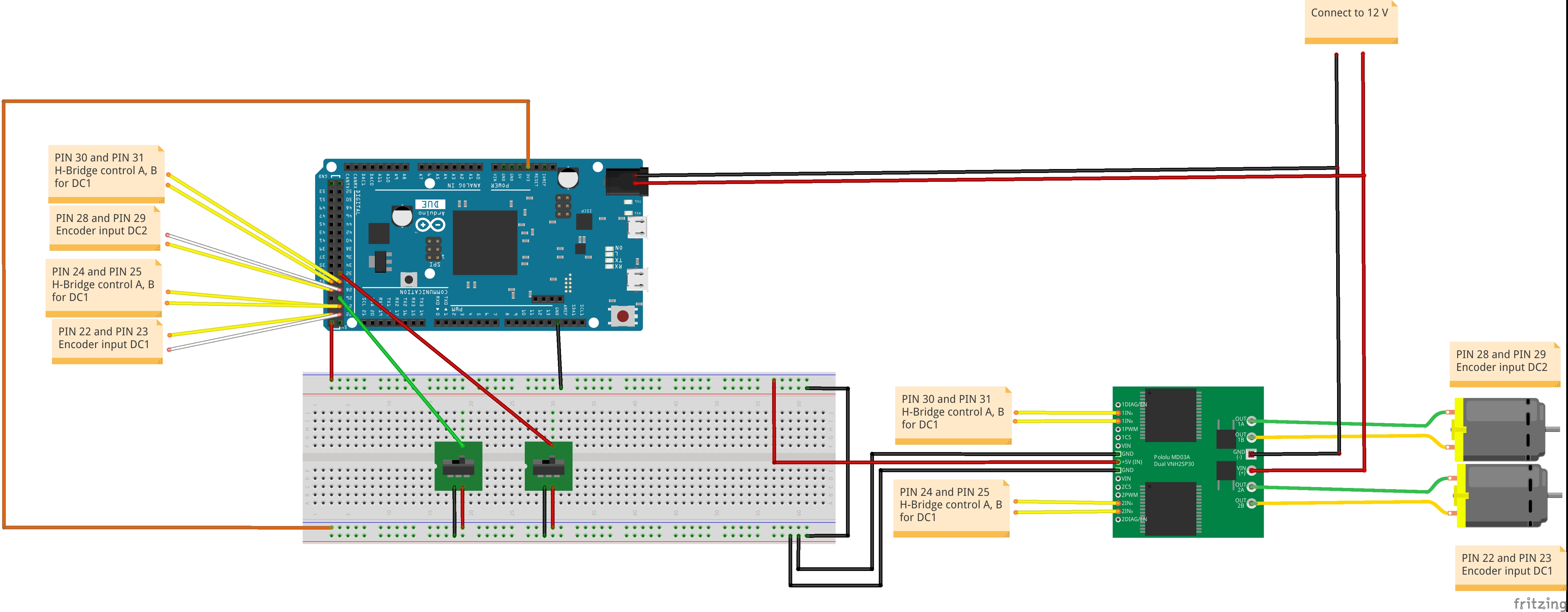
For simplicity reasons LCD is not presented on diagram. Please refer to equivalent robobo setup code:
void Robobo::createClockSetup(void)
{
    // LCD and DISPLAY MANAGER
    const int rs = 2, en = 3, d4 = 4, d5 = 5, d6 = 6, d7 = 7;
    lcd = new LiquidCrystal(rs, en, d4, d5, d6, d7);
    disp = new DisplayManager("lcd_task\0", tskIDLE_PRIORITY, lcd, 1000 );

    // DC1
    dc1 = new DCMotor(22, 23, 24, 25, 8, "dc1");
    pid1 = new PID("pid_task\0", tskHIGH_PRIORITY, 0.15,0.0000001,0,dc1);
    dc1->setControlStrategy(pid1);
    // Attaching interrupts for DC1
	attachInterrupt(digitalPinToInterrupt(22),encoderDc1_ISR, CHANGE);
	attachInterrupt(digitalPinToInterrupt(23),encoderDc1_ISR, CHANGE);
    attachInterrupt(digitalPinToInterrupt(26),limitSwitchDc1_ISR, FALLING);

    // DC2
    dc2 = new DCMotor(28, 29, 30, 31, 9, "dc2");
    pid2 = new PID("pid_task\0", tskHIGH_PRIORITY, 0.15,0.0000001,0,dc2);
    dc2->setControlStrategy(pid2);
    //// Attaching interrupts for DC2
	attachInterrupt(digitalPinToInterrupt(28),encoderDc2_ISR, CHANGE);
	attachInterrupt(digitalPinToInterrupt(29),encoderDc2_ISR, CHANGE);
    attachInterrupt(digitalPinToInterrupt(32),limitSwitchDc2_ISR, FALLING);

    // CONTROLLER
    controller = new Controller(dc1,dc2,disp);
}
- We create LiquidCrystal object. This object is taken as is from Arduino.
- Instance of
DisplayManageris ActiveObject adapter for LiquidCrystal object. I will describe concept in separate article. This particular runs at low priority. - For
dc1anddc2DC motors we create PID active object with high priority. The concept here is basically same as described in servo post and robobo software design - We are adding limit switches interrupt routines.
- At the end new controller active object is created.
Controller
Controller has following responsibilities:
- At initialization phase it holds off until all active objects are in steady
state. This is done by
initTimerwhich is defined as 3 seconds:initTimer = createOneTimeTimer( std::function<void()>(bind(&Controller::controllerFunc, this)), 3000); - When
controllerFuncis executed controller sets low voltage fordc1anddc2. For both motors in order to make them move slowly towards limit switches direction:dc1->setDirectionRight(); dc1->setVoltage(30);then runs a periodic check to see if motors did indeed stopped:
calibrationTimer = createTimer( std::function<void()>(bind(&Controller::calibrationCheck, this)), 3000); -
Motor stop condition is determined when checking flag of
DCMotorwhich is done by methodisEmergencyStopped()while the flag is set on interrupt routineslimitSwitchDc1_ISRandlimitSwitchDc2_ISR. - When both motors are emergency stopped main responsibility of controller
cahnges to main one. Controller stops
calibrationTimerand starts it once again with period value of 1 second.stopTimer(calibrationTimer); calibrationTimer = createTimer( std::function<void()>(bind(&Controller::mainFunc, this)), 1000); - Now every second controller increases seconds counter and calculates
requested motors position corresponding with minutes and seconds
void mainFunc() { seconds++; minutes = seconds/60; secondPos = -140 * seconds; minutesPos = -140 * minutes; a->setRequestedPosition(secondPos); b->setRequestedPosition(minutesPos); ... } - Once requested position is set PID objects takes care of rest so controller
job is finished until next period driven by
calibrationTimer.
Video description
TBD
Value in Tests
TBD